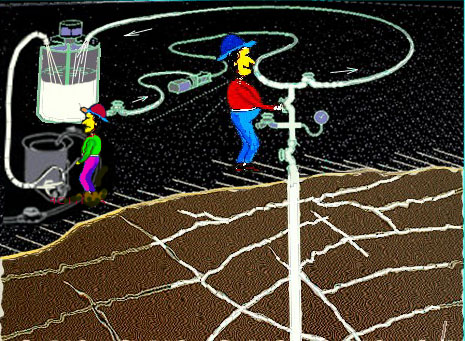
This is a simple layout of the grouting equipment. The grout is mixed in the mixer at left, and then sent to the agitator, from which a pump is used to pump it along the circulation line to the grout hole. Grout not used there is pumped back to the agitator.
In this sketch the grouting has progressed to the stage where the cracks have been partly filled with grout, but you will, of course, be starting with a fresh hole.
In this simulation the gear on the surface is not shown in further sketches. For explanations of the
terminology and criteria used consult the accompanying programmes.
And now we come to running the
simulation. The pretend grout hole is 20 feet deep [6 metres, say] and is vertical. The grout does not
contain additives.
GROUTING THE HOLE
Assume that the cracking system reached by this hole has the following properties:
1. The water test before grouting gave a lugeon value in the 'medium' range.
This range might be regarded as a test result in the range between 8to10 and 25to40
lugeons.
2. Cracks are generally wider than about 0.030 inches [0.8 mm] and less than about 0.050 inches [1.25mm] open, and are in sufficient number to provide easy travel for the grout through the cracking system.
A suitable starting water:cement ratio for these could be 2:1 (by volume).
The starting pressure, measured at the surface, should be 15 psi [1 bar] for the first few minutes.
Assume that no problems develop, such as leaks, connections, or rock movements, and that the grouting proceeds smoothly. The pressure can therefore be gradually increasted to the recommended limit for sound rock, which is 25 psi [2 bar] for this depth of hole.
At the end of the first 15 minutes on an actual grouting job checks should be made to make sure that everything is going right. These checks involve observations of the rate of drop of the grout surface in the agitator, and of the behaviour of the pressure gauge, but because we cannot simulate these, we will merely state what they are doing.
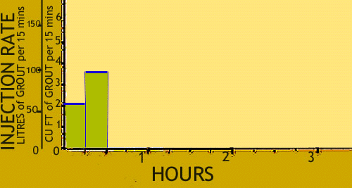
At 15 minutes assume that the amount of grout taken down the hole, so far, is 2 cubic feet [54 litres].
After that the hole continues to take grout at a reasonable rate. At the end of 30 minutes we can pretend that the rate has increased in the manner in which it does in many jobs, and the grout taken is a further 3.6 cu ft [97 litres] It is then helpful to graph the grout behaviour:-

This type of plot is used frequently in this simulation. It shows the RATE of grout taken. The grout speeds up as the pressure rises and it is this speed which is one of the factors which show how the grout application is going. The rate is measured in cubic feet per 15 minutes or litres per 15 minutes and is shown here in bar form to match readings taken at 15 minute intervals. Some jobs have continuous reading arrangements and this produces a curve rather than bars, but this is not shown at this juncture. The amount of cement in the grout is read off tables or obtained from computer programmes.
To simplify things, the cement injected is specified here in bags. These are 94 pound bags if traditional units are pretended to be in use, or 40 kilogramme bags for metric. They are near enough the same for the purposes here.The amount of cement injected so far is 2.26 bags contained in 5.6 cu ft [151 litres] of grout.